STM32Cube HAL and Nucleo-F401RE: debugging and unit testing
The goal of this tutorial is to demonstrate how simple it is to use PlatformIO IDE for VSCode to develop, run and debug a basic blink project with STM32Cube framework for STM32 Nucleo-F401RE board.
Level: Intermediate
Platforms: Windows, Mac OS X, Linux
Requirements:
Downloaded and installed PlatformIO IDE for VSCode
Install drivers for ST-LINK debug tool
ST Nucleo F401RE development board
Setting Up the Project
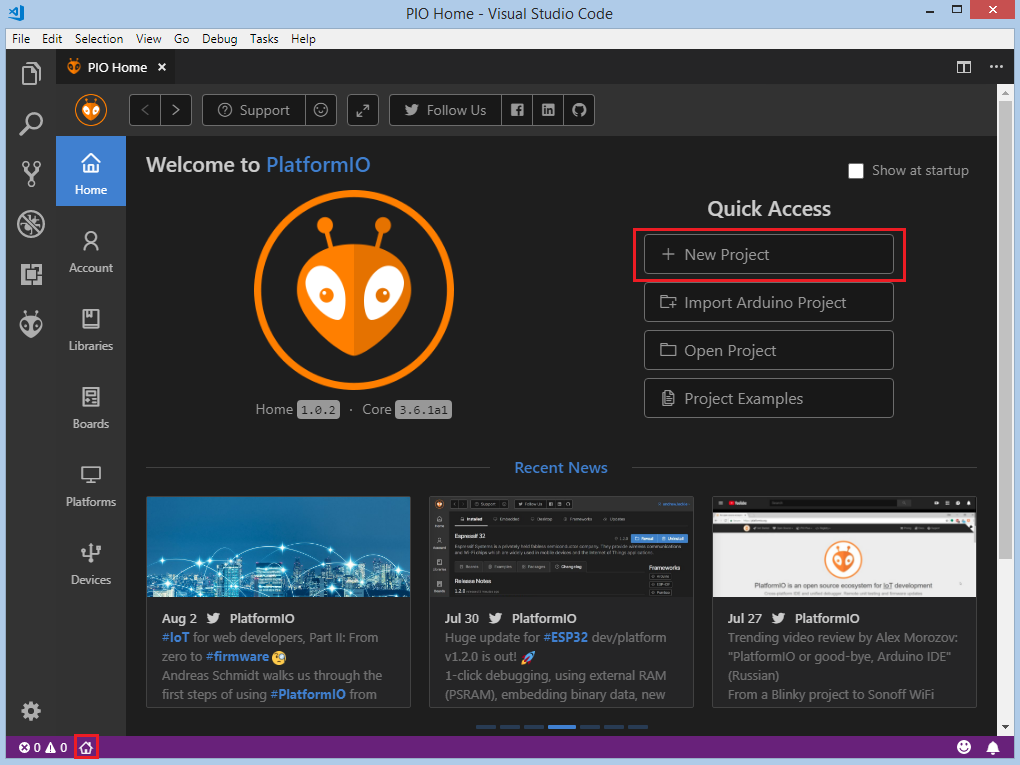
At first step, we need to create a new project using PlatformIO Home Page (to open this page just press Home icon on the toolbar):
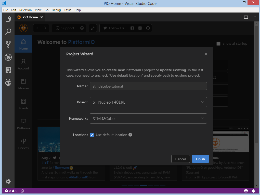
On the next step, we need to select ST Nucleo-F401RE as a development board, STM32Cube as a framework and a path to the project location (or use the default one):
Processing the selected project may take some amount of time (PlatformIO will download and install all required packages) and after these steps, we have a fully configured project that is ready for developing code with STM32Cube framework.
Adding Code to the Generated Project
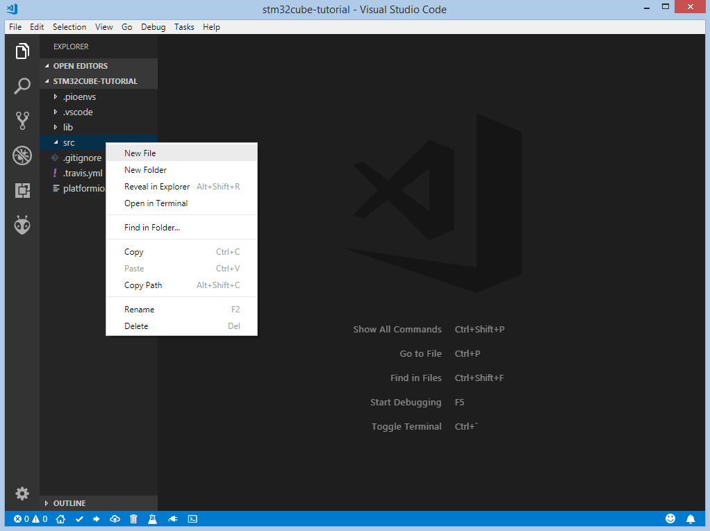
Let’s add some actual code to the project. Firstly, we create two main files main.c and main.h in the src_dir folder. Right click on the src in the project window:
Add next content to main.h:
#ifndef MAIN_H
#define MAIN_H

#include "stm32f4xx_hal.h"

#define LED_PIN                                GPIO_PIN_5
#define LED_GPIO_PORT                          GPIOA
#define LED_GPIO_CLK_ENABLE()                  __HAL_RCC_GPIOA_CLK_ENABLE()

#endif // MAIN_H
Add this code to main.c:
#include "main.h"

void LED_Init();

int main(void)
{
  HAL_Init();
  LED_Init();

  while (1)
  {
    HAL_GPIO_TogglePin(LED_GPIO_PORT, LED_PIN);
    HAL_Delay(1000);
  }
}

void LED_Init()
{
  LED_GPIO_CLK_ENABLE();
  GPIO_InitTypeDef GPIO_InitStruct;
  GPIO_InitStruct.Pin = LED_PIN;
  GPIO_InitStruct.Mode = GPIO_MODE_OUTPUT_PP;
  GPIO_InitStruct.Pull = GPIO_PULLUP;
  GPIO_InitStruct.Speed = GPIO_SPEED_HIGH;
  HAL_GPIO_Init(LED_GPIO_PORT, &GPIO_InitStruct);
}

void SysTick_Handler(void)
{
  HAL_IncTick();
}
After this step, we created a basic blink project that is ready for compiling and uploading.
Compiling and Uploading the Firmware
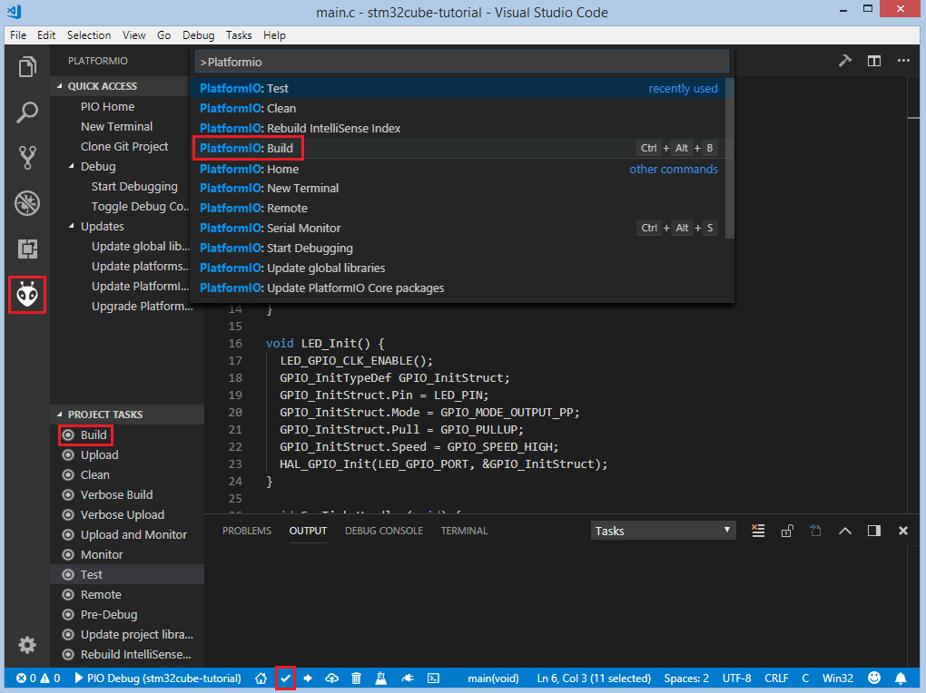
Now we can build the project. To compile firmware we can use next options:
Build option on the Project Tasks menu, Build button on PlatformIO Toolbar, using Command Palette View: Command Palette > PlatformIO: Build, using Task Menu Tasks: Run Task... > PlatformIO: Build or via hotkeys cmd-alt-b / ctrl-alt-b:
If everything went well, we should see the successful result in the terminal window:

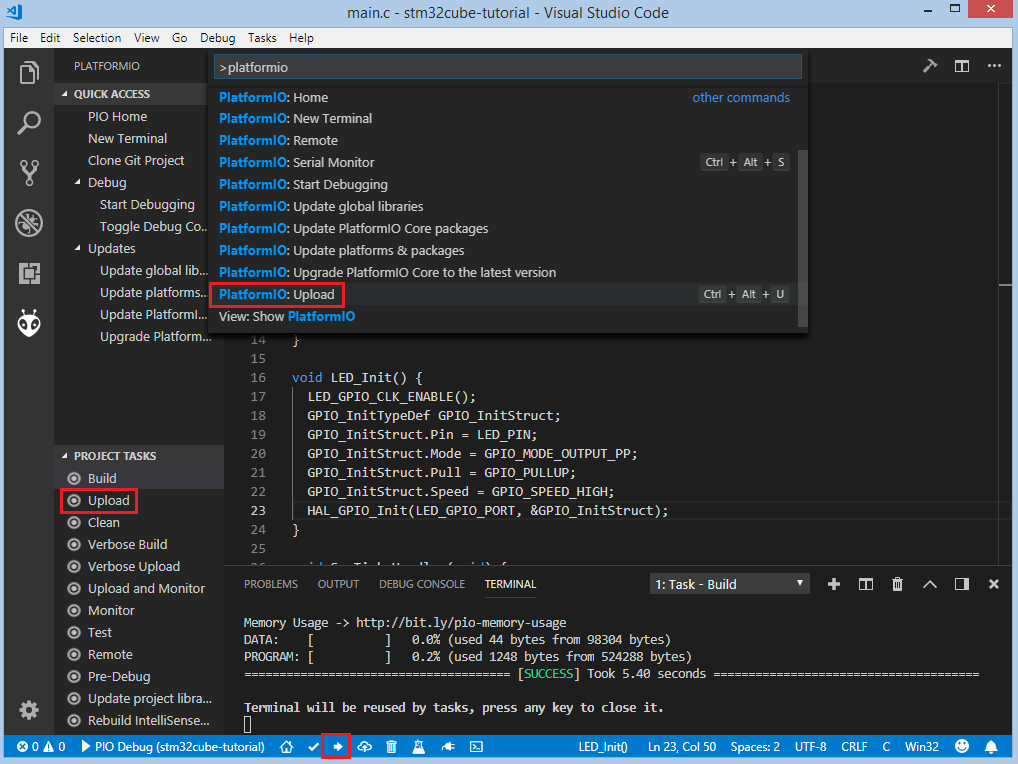
To upload the firmware to the board we can use next options:
Upload option on the Project Tasks menu, Upload button on PlatformIO Toolbar, using Command Palette View: Command Palette > PlatformIO: Upload, using Task Menu Tasks: Run Task... > PlatformIO: Upload or via hotkeys cmd-alt-u / ctrl-alt-u:
After successful uploading, the green LED2 should start blinking.
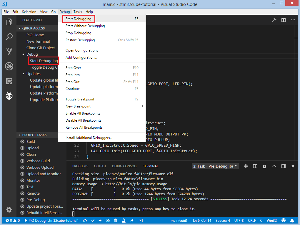
Debugging the Firmware
Debugging offers the easiest way to debug your board. To start debugging session you can use Start debugging option in PlatformIO Quick Access menu, Debug: Start debugging from the top menu or hotkey button F5:
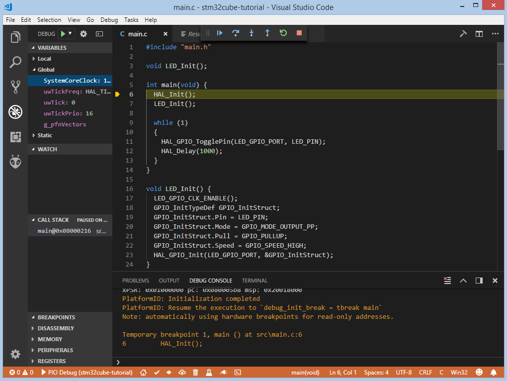
We need to wait some time while PlatformIO is initializing debug session and when the first line after the main function is highlighted we are ready to debug:
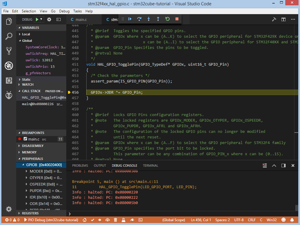
We can walk through the code using control buttons, set breakpoints, see peripheral registers, add variables to Watch window:
Writing Unit Tests
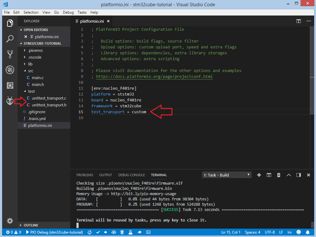
Now let’s write some tests using the Unit Testing solution that can help us test code directly on the target board. We will use the Unity testing framework. Since there is no default configuration for the STM32Cube framework, we will provide a Custom unity_config.h.
Also, we need to create a new folder test where the tests and custom
Unity configuration (described next) will be located:
We will use USART2 on ST Nucleo-F401RE board because it’s directly connected
to the STLink debug interface and in OS it can be visible as a Virtual Com Port,
so we don’t need any additional USB-UART converter. To implement the custom
Unity configuration we need to create two
files unity_config.h and unity_config.c and put them in
the test_dir in the root folder of our project.
Implementation of unity_config.h:
#ifndef UNITY_CONFIG_H
#define UNITY_CONFIG_H

#ifndef NULL
#ifndef __cplusplus
#define NULL (void*)0
#else
#define NULL 0
#endif
#endif

#ifdef __cplusplus
extern "C"
{
#endif

void unityOutputStart();
void unityOutputChar(char);
void unityOutputFlush();
void unityOutputComplete();

#define UNITY_OUTPUT_START()    unityOutputStart()
#define UNITY_OUTPUT_CHAR(c)    unityOutputChar(c)
#define UNITY_OUTPUT_FLUSH()    unityOutputFlush()
#define UNITY_OUTPUT_COMPLETE() unityOutputComplete()

#ifdef __cplusplus
}
#endif /* extern "C" */

#endif /* UNITY_CONFIG_H */
Implementation of unity_config.c:
#include "unity_config.h"
#include "stm32f4xx_hal.h"

#define USARTx USART2
#define USARTx_CLK_ENABLE() __HAL_RCC_USART2_CLK_ENABLE()
#define USARTx_CLK_DISABLE() __HAL_RCC_USART2_CLK_DISABLE()
#define USARTx_RX_GPIO_CLK_ENABLE() __HAL_RCC_GPIOA_CLK_ENABLE()
#define USARTx_TX_GPIO_CLK_ENABLE() __HAL_RCC_GPIOA_CLK_ENABLE()
#define USARTx_RX_GPIO_CLK_DISABLE() __HAL_RCC_GPIOA_CLK_DISABLE()
#define USARTx_TX_GPIO_CLK_DISABLE() __HAL_RCC_GPIOA_CLK_DISABLE()

#define USARTx_FORCE_RESET() __HAL_RCC_USART2_FORCE_RESET()
#define USARTx_RELEASE_RESET() __HAL_RCC_USART2_RELEASE_RESET()

#define USARTx_TX_PIN GPIO_PIN_2
#define USARTx_TX_GPIO_PORT GPIOA
#define USARTx_TX_AF GPIO_AF7_USART2
#define USARTx_RX_PIN GPIO_PIN_3
#define USARTx_RX_GPIO_PORT GPIOA
#define USARTx_RX_AF GPIO_AF7_USART2

static UART_HandleTypeDef UartHandle;

void unityOutputStart()
{
  GPIO_InitTypeDef GPIO_InitStruct;

  USARTx_TX_GPIO_CLK_ENABLE();
  USARTx_RX_GPIO_CLK_ENABLE();

  USARTx_CLK_ENABLE();

  GPIO_InitStruct.Pin = USARTx_TX_PIN;
  GPIO_InitStruct.Mode = GPIO_MODE_AF_PP;
  GPIO_InitStruct.Pull = GPIO_PULLUP;
  GPIO_InitStruct.Speed = GPIO_SPEED_FAST;
  GPIO_InitStruct.Alternate = USARTx_TX_AF;

  HAL_GPIO_Init(USARTx_TX_GPIO_PORT, &GPIO_InitStruct);

  GPIO_InitStruct.Pin = USARTx_RX_PIN;
  GPIO_InitStruct.Alternate = USARTx_RX_AF;

  HAL_GPIO_Init(USARTx_RX_GPIO_PORT, &GPIO_InitStruct);
  UartHandle.Instance = USARTx;

  UartHandle.Init.BaudRate = 115200;
  UartHandle.Init.WordLength = UART_WORDLENGTH_8B;
  UartHandle.Init.StopBits = UART_STOPBITS_1;
  UartHandle.Init.Parity = UART_PARITY_NONE;
  UartHandle.Init.HwFlowCtl = UART_HWCONTROL_NONE;
  UartHandle.Init.Mode = UART_MODE_TX_RX;
  UartHandle.Init.OverSampling = UART_OVERSAMPLING_16;

  if (HAL_UART_Init(&UartHandle) != HAL_OK)
  {
    while (1)
    {
    }
  }
}

void unityOutputChar(char c)
{
  HAL_UART_Transmit(&UartHandle, (uint8_t *)(&c), 1, 1000);
}

void unityOutputFlush() {}

void unityOutputComplete()
{
  USARTx_CLK_DISABLE();
  USARTx_RX_GPIO_CLK_DISABLE();
  USARTx_TX_GPIO_CLK_DISABLE();
}
Now we need to add some test cases. Tests can be added to a single C file that may include multiple tests. First of all, we need to add three default functions: setUp, tearDown and main. setUp and tearDown are used to initialize and finalize test conditions. Implementations of these functions are not required for running tests but if you need to initialize some variables before you run a test, you use the setUp function and if you need to clean up variables you use tearDown function. In our example, we will use these functions to accordingly initialize and deinitialize LED. main function acts as a simple program where we describe our test plan.
Let’s add a new file test_main.c to the folder test. Next basic tests for blinking routine will be implemented in this file:
test_led_builtin_pin_numberensures thatLED_PINhas the correct valuetest_led_state_hightests functionsHAL_GPIO_WritePinandHAL_GPIO_ReadPinwithGPIO_PIN_SETvaluetest_led_state_lowtests functionsHAL_GPIO_WritePinandHAL_GPIO_ReadPinwithGPIO_PIN_RESETvalue
Note
2 sec delay is required since the board doesn’t support software resetting via
Serial.DTR/RTS
#include "../src/main.h"
#include <unity.h>

void setUp(void)
{
  LED_GPIO_CLK_ENABLE();
  GPIO_InitTypeDef GPIO_InitStruct;
  GPIO_InitStruct.Pin = LED_PIN;
  GPIO_InitStruct.Mode = GPIO_MODE_OUTPUT_PP;
  GPIO_InitStruct.Pull = GPIO_PULLUP;
  GPIO_InitStruct.Speed = GPIO_SPEED_HIGH;
  HAL_GPIO_Init(LED_GPIO_PORT, &GPIO_InitStruct);
}

void tearDown(void)
{
  HAL_GPIO_DeInit(LED_GPIO_PORT, LED_PIN);
}

void test_led_builtin_pin_number(void)
{
  TEST_ASSERT_EQUAL(GPIO_PIN_5, LED_PIN);
}

void test_led_state_high(void)
{
  HAL_GPIO_WritePin(LED_GPIO_PORT, LED_PIN, GPIO_PIN_SET);
  TEST_ASSERT_EQUAL(GPIO_PIN_SET, HAL_GPIO_ReadPin(LED_GPIO_PORT, LED_PIN));
}

void test_led_state_low(void)
{
  HAL_GPIO_WritePin(LED_GPIO_PORT, LED_PIN, GPIO_PIN_RESET);
  TEST_ASSERT_EQUAL(GPIO_PIN_RESET, HAL_GPIO_ReadPin(LED_GPIO_PORT, LED_PIN));
}

int main()
{
  HAL_Init();      // initialize the HAL library
  HAL_Delay(2000); // service delay

  UNITY_BEGIN();
  RUN_TEST(test_led_builtin_pin_number);

  for (unsigned int i = 0; i < 5; i++)
  {
    RUN_TEST(test_led_state_high);
    HAL_Delay(500);
    RUN_TEST(test_led_state_low);
    HAL_Delay(500);
  }

  UNITY_END(); // stop unit testing

  while (1)
  {
  }
}

void SysTick_Handler(void)
{
  HAL_IncTick();
}
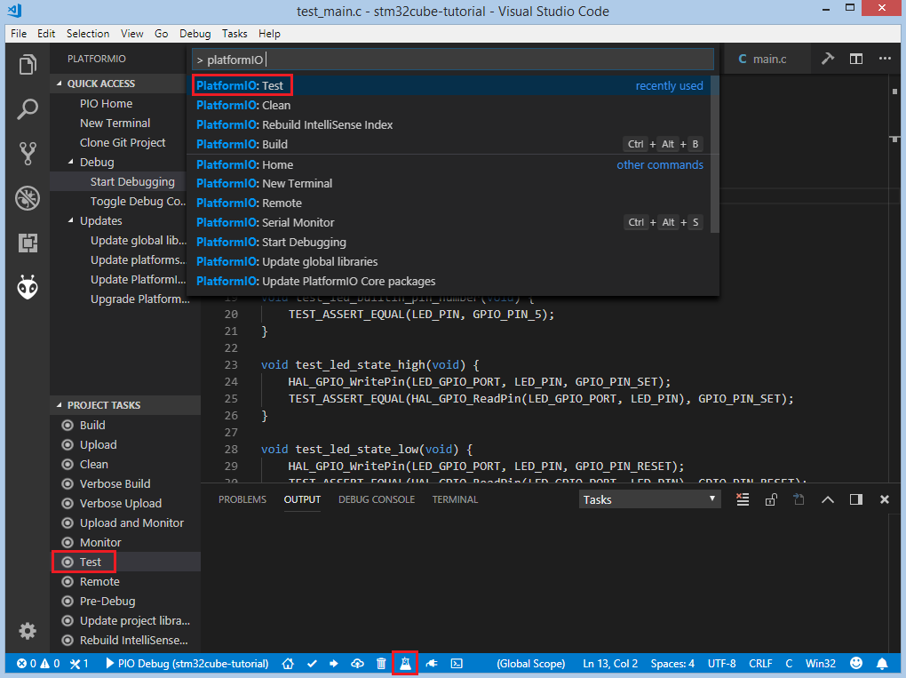
Now we are ready to upload tests to the board. To do this we can use Test option from the Project Tasks menu, Tasks: Run Task... > PlatformIO Test option from the top menu or Test button on PlatformIO Toolbar:
After processing we should see a detailed report about the testing results:
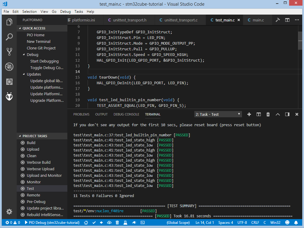
Congratulations! As we can see from the report, all our tests went successfully!
Conclusion
Now we have a decent template that we can improve for our next more complex projects.
Project Source Code
The source code of this tutorial is available at https://github.com/platformio/platformio-examples/tree/develop/unit-testing/stm32cube