Get started with Arduino and ESP32-DevKitC: debugging and unit testing
The goal of this tutorial is to demonstrate how simple it is to use PlatformIO IDE for VSCode to develop, run and debug a simple project with the Arduino framework for the ESP32-DevKitC board.
Level: Beginner
Platforms: Windows, Mac OS X, Linux
- Requirements:
Downloaded and installed PlatformIO IDE for VSCode
Olimex ARM-USB-OCD or Olimex ARM-USB-TINY adapter for debugging
Setting Up the Project
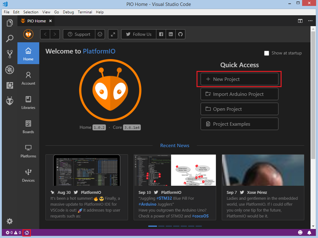
First, we need to create a new project using the PlatformIO Home Page (to open this page, just press the Home icon on the toolbar):
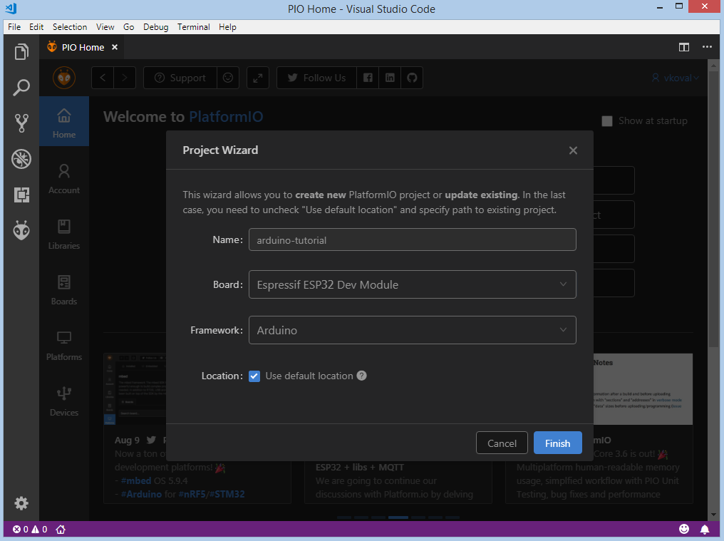
Next, we need to select Espressif ESP32 Dev Module as a development board, Arduino as a framework and a path to the project location (or use the default one):
Processing the selected project may take some time (PlatformIO will download and install all required packages). After that, we have a fully configured project that is ready for developing code with the Arduino framework.
Adding Code to the Generated Project
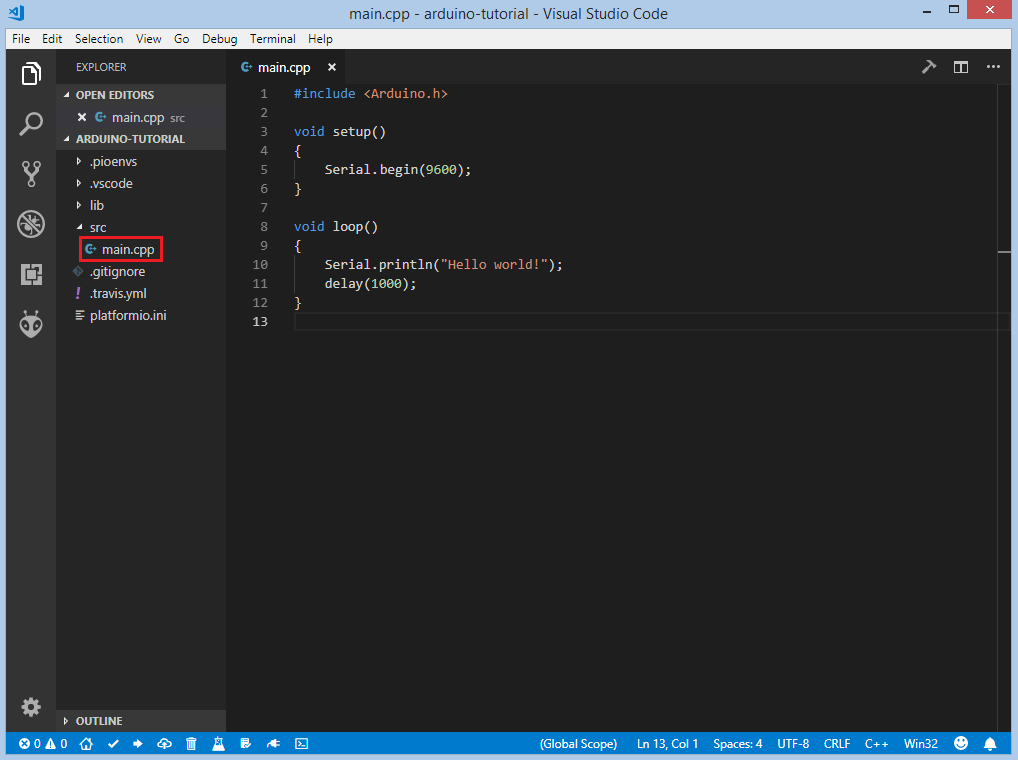
Let’s add some actual code to the project. Firstly, we open a default main file named main.cpp in the src_dir folder and replace its content with following:
#include <Arduino.h>

void setup()
{
    Serial.begin(9600);
}

void loop()
{
    Serial.println("Hello world!");
    delay(1000);
}
We have now created a basic project ready for compiling and uploading.
Compiling and Uploading the Firmware
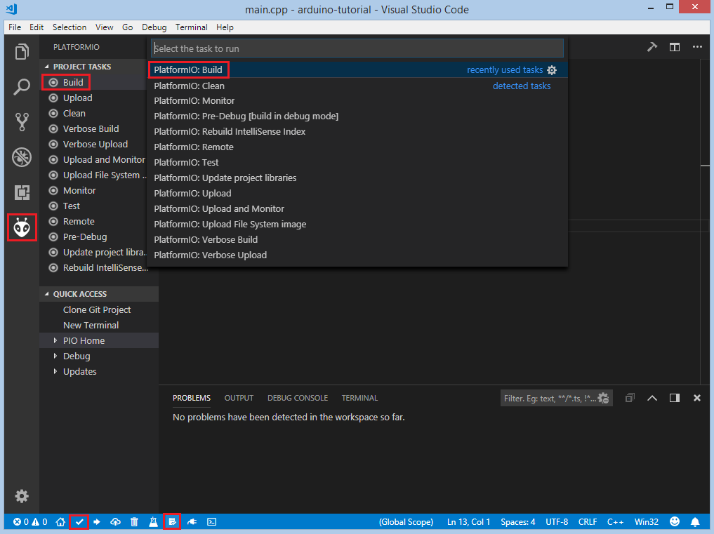
Now we can build the project. There are several ways to compile firmware:
Build option in the
Project Tasksmenu,Build button in PlatformIO Toolbar,
Task Menu:
Tasks: Run Task... > PlatformIO: Build, or in the PlatformIO Toolbar,Command Palette:
View: Command Palette > PlatformIO: Build, orvia hotkeys
cmd-alt-b / ctrl-alt-b
Marked in red:
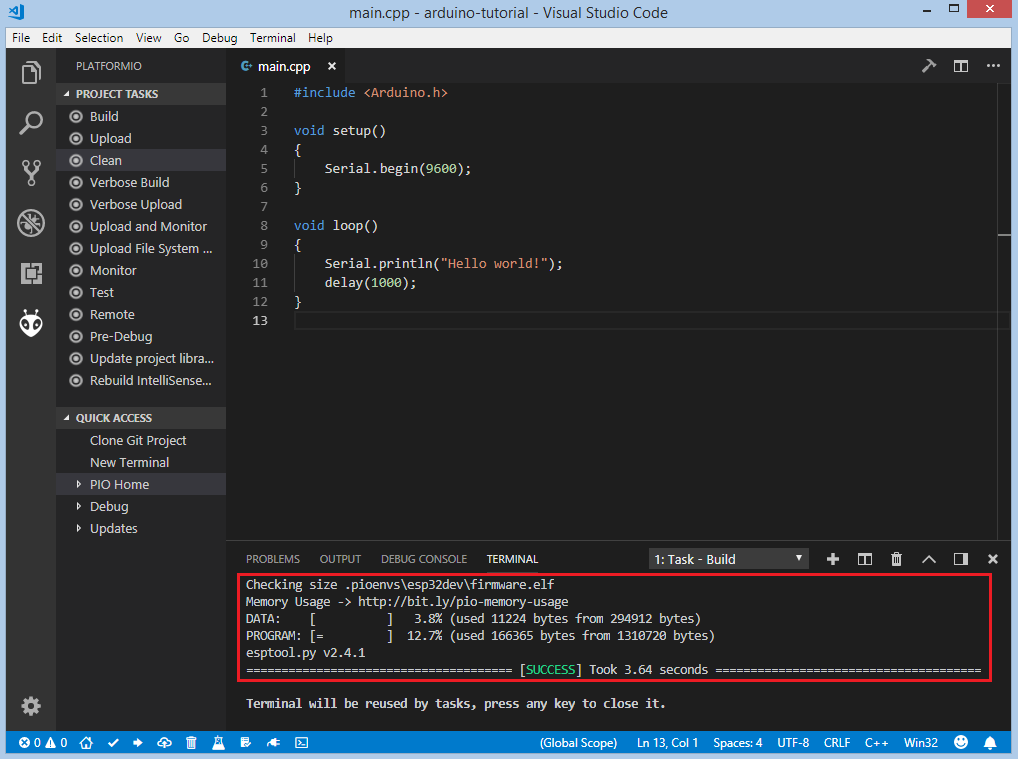
If everything went well, we should see a Success message in the terminal window:
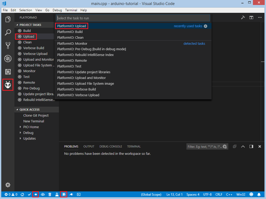
There are also several ways to upload the firmware to the board:
Upload option in the
Project Tasksmenu,Upload button in PlatformIO Toolbar,
Command Palette:
View: Command Palette > PlatformIO: Upload,using the Task Menu:
Tasks: Run Task... > PlatformIO: Upload, orvia hotkeys:
cmd-alt-u / ctrl-alt-u:
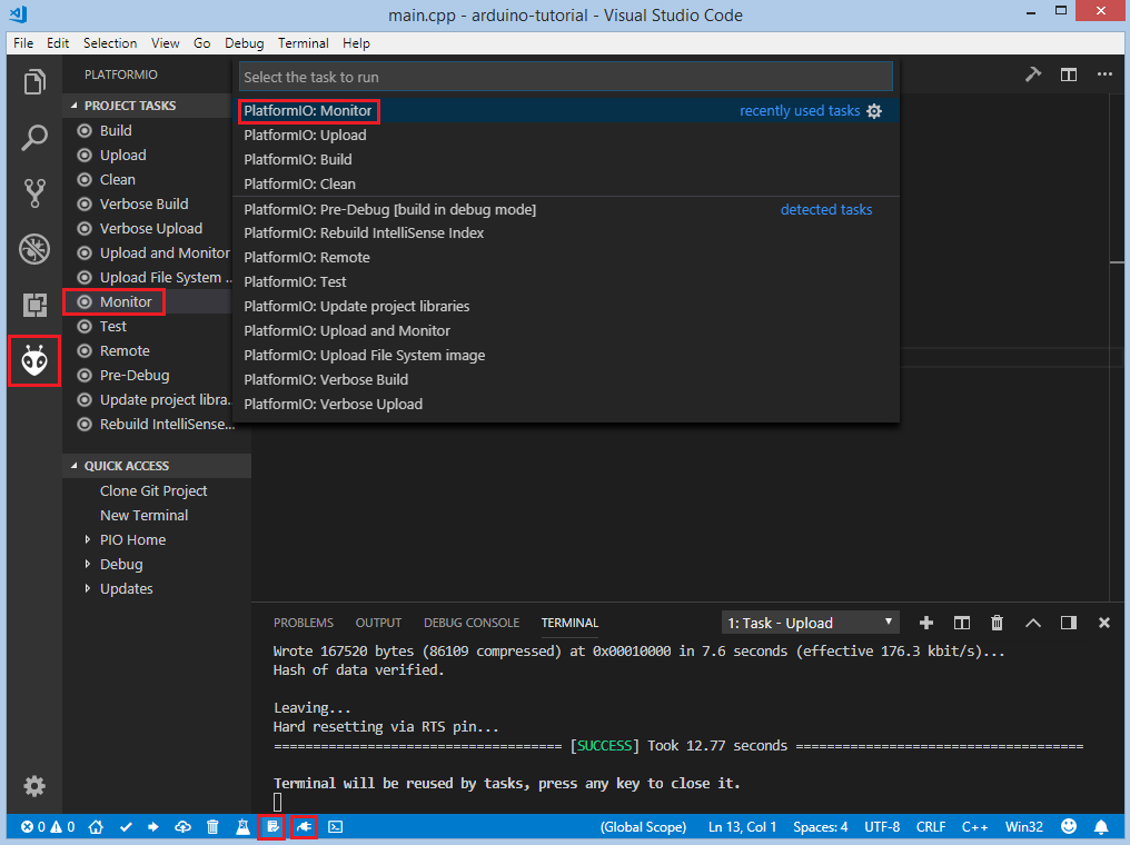
After uploading, we need to check if the firmware is uploaded correctly. To do this, open the serial monitor and check that the message from the board is received. To open the serial monitor, we can use the following options:
Monitor option in the
Project Tasksmenu,Serial Monitor button in the PlatformIO Toolbar,
Command Palette:
View: Command Palette > PlatformIO: Monitor, orTask Menu:
Tasks: Run Task... > PlatformIO: Monitor:
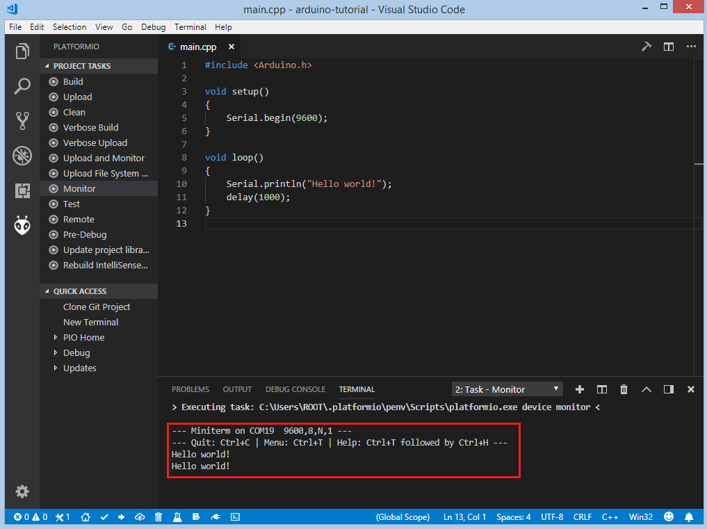
If the firmware works as expected, the message from the board can be observed in the terminal window:
Debugging the Firmware
Setting Up the Hardware
In order to use a JTAG probe with an ESP32, we need to connect the following pins:
ESP32 pin |
JTAG probe pin |
|---|---|
|
|
|
|
|
|
|
|
|
|
|
|
|
|
Debugging offers the easiest way to debug the board. Firstly, we need to specify debug_tool in “platformio.ini” (Project Configuration File). In this tutorial, an Olimex ARM-USB-OCD-H debug probe is used:
[env:esp32dev]
platform = espressif32
board = esp32dev
framework = arduino
debug_tool = olimex-arm-usb-ocd-h
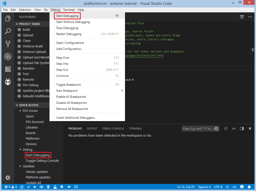
To start the debug session we can use the following methods:
Debug: Start debuggingin the top menu,Start Debuggingoption in the Quick Access menu, orhotkey button
F5:
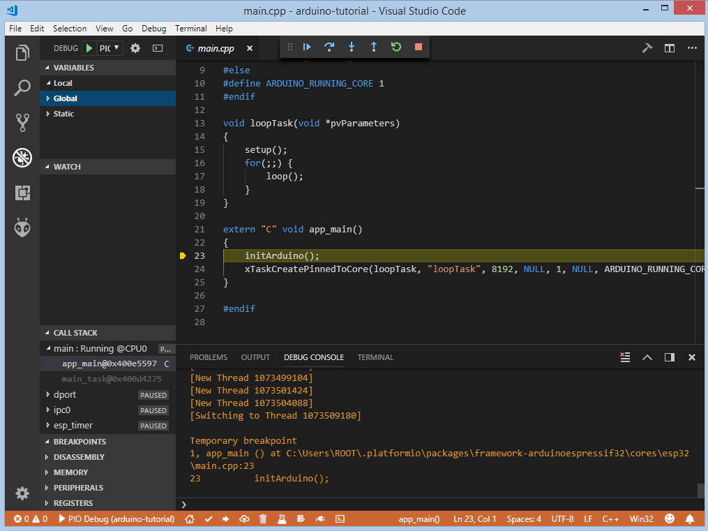
We need to wait some time while PlatformIO initializes the debug session, and are ready to debug when the first line after the main function is highlighted.
Please wait when debugging session is stopped at the first line of
app_main()functionWARNING! Please set a breakpoint at
void loopTask(void *pvParameters)(line 13 in the screenshot below - this line can change between releases)Now, please press CONTINUE/RUN button on debugging toolbar (right arrow icon)
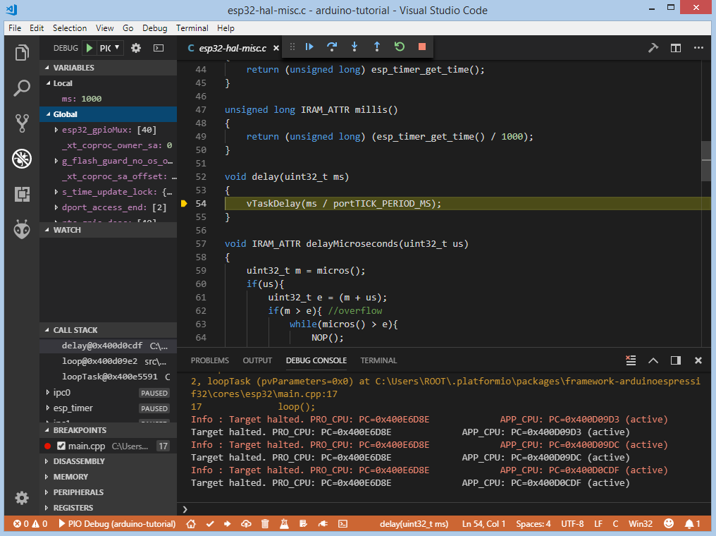
The debugging session should stop at the first line of the
void loopTask(void *pvParameters)functionNow, navigate to your Arduino setup/loop code and do classic debugging.
We can walk through the code using control buttons, set breakpoints, and add variables to the Watch window:
Writing Unit Tests
Unit Testing test cases can be added to a single file that may include
multiple tests. First of all, in this file, we need to add four default
functions: setUp, tearDown, setup and loop.
Functions setUp and tearDown are used to initialize and finalize
test conditions. Implementations of these functions are not required for running
tests, but if you need to initialize some variables before you run a test,
use the setUp function. Likewise, if you need to clean up variables,
use tearDown function. In our example we will use these functions to
respectively initialize and deinitialize LED states. The setup and loop
functions act as a simple Arduino program where we describe our test plan.
Let’s create a test folder in the root of the project and add a new file, test_main.cpp, to this folder. Next, basic tests for String class will be implemented in this file:
test_string_concattests the concatenation of two stringstest_string_substringtests the correctness of the substring extractiontest_string_index_ofensures that the string returns the correct index of the specified symboltest_string_equal_ignore_casetests case-insensitive comparison of two stringstest_string_to_upper_casetests conversion of the string to upper-casetest_string_replacetests the correctness of the replacing operation
#include <Arduino.h>
#include <unity.h>

String STR_TO_TEST;

void setUp(void) {
    // set stuff up here
    STR_TO_TEST = "Hello, world!";
}

void tearDown(void) {
    // clean stuff up here
    STR_TO_TEST = "";
}

void test_string_concat(void) {
    String hello = "Hello, ";
    String world = "world!";
    TEST_ASSERT_EQUAL_STRING(STR_TO_TEST.c_str(), (hello + world).c_str());
}

void test_string_substring(void) {
    TEST_ASSERT_EQUAL_STRING("Hello", STR_TO_TEST.substring(0, 5).c_str());
}

void test_string_index_of(void) {
    TEST_ASSERT_EQUAL(7, STR_TO_TEST.indexOf('w'));
}

void test_string_equal_ignore_case(void) {
    TEST_ASSERT_TRUE(STR_TO_TEST.equalsIgnoreCase("HELLO, WORLD!"));
}

void test_string_to_upper_case(void) {
    STR_TO_TEST.toUpperCase();
    TEST_ASSERT_EQUAL_STRING("HELLO, WORLD!", STR_TO_TEST.c_str());
}

void test_string_replace(void) {
    STR_TO_TEST.replace('!', '?');
    TEST_ASSERT_EQUAL_STRING("Hello, world?", STR_TO_TEST.c_str());
}

void setup()
{
    delay(2000); // service delay
    UNITY_BEGIN();

    RUN_TEST(test_string_concat);
    RUN_TEST(test_string_substring);
    RUN_TEST(test_string_index_of);
    RUN_TEST(test_string_equal_ignore_case);
    RUN_TEST(test_string_to_upper_case);
    RUN_TEST(test_string_replace);

    UNITY_END(); // stop unit testing
}

void loop()
{
}
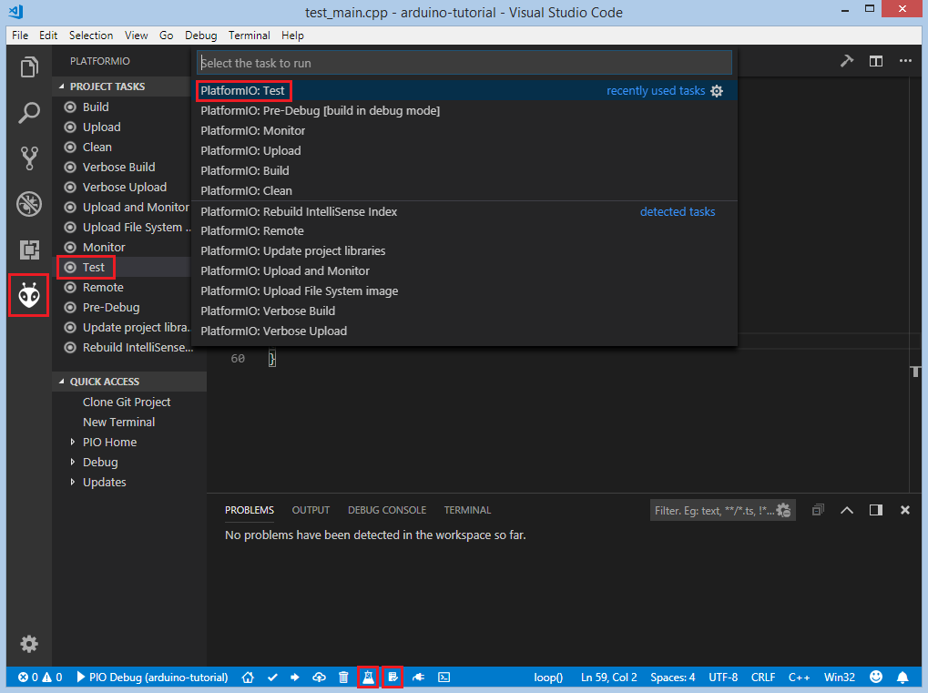
Now we are ready to upload tests to the board. To do this we can use the following:
Test button on PlatformIO Toolbar,
Test option in the
Project Tasksmenu, orTasks: Run Task... > PlatformIO Testin the top menu:
After processing, we should see a detailed report about the testing results:
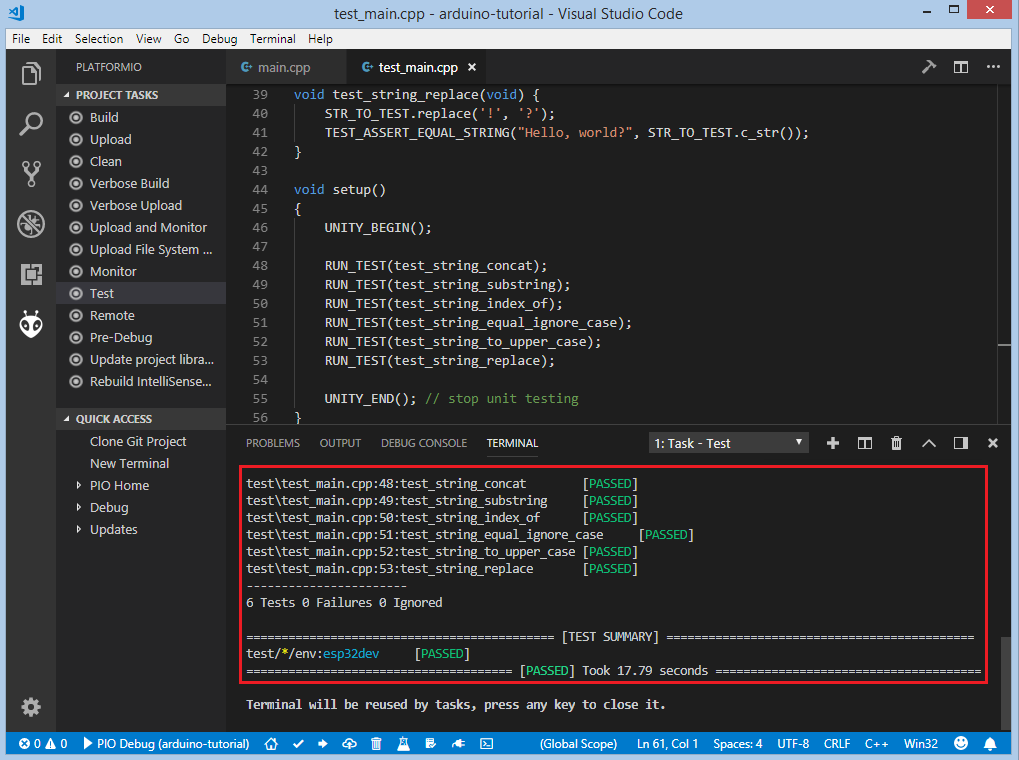
As we can see from the report, all our tests were successful!
Adding Bluetooth LE features
Now let’s create a basic application that can interact with other BLE devices (e.g phones). For example, the following code declares a BLE characteristic whose value can be printed to the serial port:
#include <Arduino.h>
#include <BLEDevice.h>
#include <BLEUtils.h>
#include <BLEServer.h>

#define SERVICE_UUID        "4fafc201-1fb5-459e-8fcc-c5c9c331914b"
#define CHARACTERISTIC_UUID "beb5483e-36e1-4688-b7f5-ea07361b26a8"

class MyCallbacks: public BLECharacteristicCallbacks {
    void onWrite(BLECharacteristic *pCharacteristic) {
      std::string value = pCharacteristic->getValue();
      if (value.length() > 0) {
        Serial.print("\r\nNew value: ");
        for (int i = 0; i < value.length(); i++)
          Serial.print(value[i]);
        Serial.println();
      }
    }
};

void setup() {
  Serial.begin(9600);

  BLEDevice::init("ESP32 BLE example");
  BLEServer *pServer = BLEDevice::createServer();
  BLEService *pService = pServer->createService(SERVICE_UUID);
  BLECharacteristic *pCharacteristic = pService->createCharacteristic(
                                         CHARACTERISTIC_UUID,
                                         BLECharacteristic::PROPERTY_READ |
                                         BLECharacteristic::PROPERTY_WRITE
                                       );

  pCharacteristic->setCallbacks(new MyCallbacks());

  pCharacteristic->setValue("Hello World");
  pService->start();

  BLEAdvertising *pAdvertising = pServer->getAdvertising();
  pAdvertising->start();
}

void loop() {
  delay(2000);
}
Now we can compile and upload this program to the board as described in the previous sections. To verify that our application works as expected, we can use any Android smartphone with the BLE feature and Nordic nRF Connect tool.
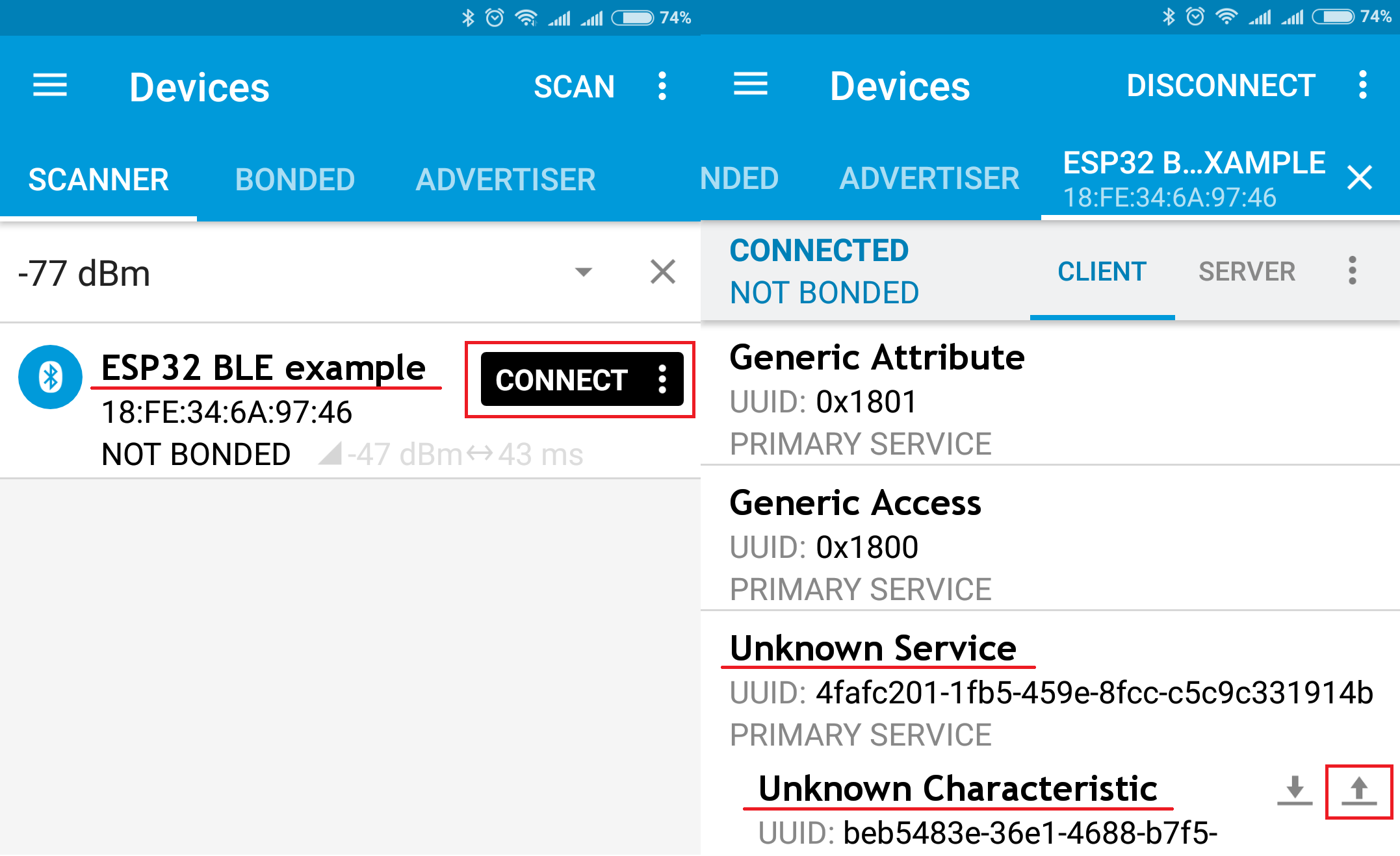
At first, we need to scan all advertising BLE devices and connect to the device called ESP32 BLE example.
After successful connection to the board, we should see one “Unknown Service” with one “Unknown Characteristic” field:
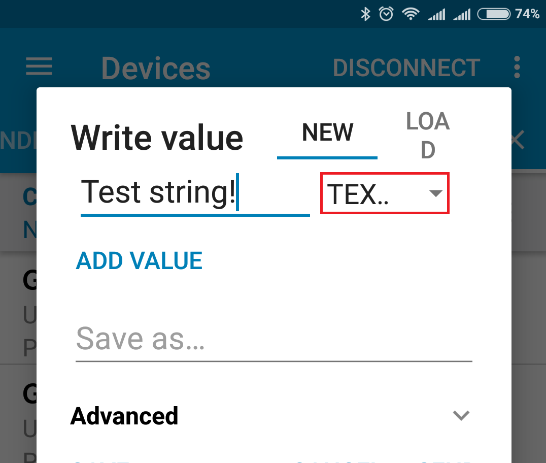
To set the value, we need to send new text to the BLE characteristic:
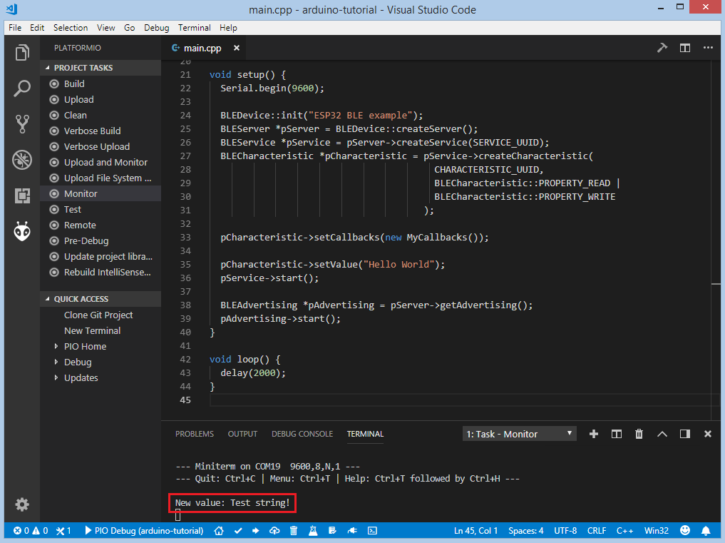
The change of the value is printed to the serial monitor:
Conclusion
Now we have a project template for the ESP32-DevKitC board that we can use as boilerplate for later projects.